 |
|
RATCU - PINOUT, INSTALLATION
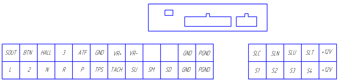
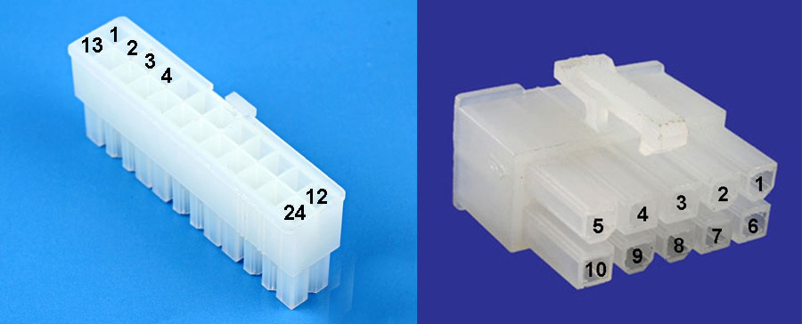
24PIN:
- SOUT – speed output, 0-12V sine
- BTN – unlock the torque converter input or speed correction (downshift), circuit to +12V
- HALL – speed sensor input (Hall sensor) 5-12V sine
- 3 – overdrive signal input, circuit to +12V
- ATF – temperature signal input, circuit to negative
- GND – input negative
- VR+ - inductive speed sensor input (SP2) + (polarity is important), reed switch input (negative)
- VR- - inductive speed sensor input (SP2) – (polarity is important)
- +5V - output +5v for TPS sensor (since version 3.0)
- GND – input negative
- PGND – input power negative (maximum loaded interference)
- L – input signal selector, L position, circuit to +12V
- 2 – input signal selector, 2 position, circuit to +12V
- N – input signal selector, N position, circuit to +12V
- R – input signal selector, R position, circuit to +12V
- P – input signal selector, P position, circuit to +12V
- TPS – Throttle position sensor input, sine 0-5V (maximum 5 volt)
- TACH – tachometer input signal, sine 0-12V
- SU – button input SHIFT UP (used in manual mode), mode POWER, circuit to negative
- SM – button input SHIFT MODE (launches manual mode), circuit to +12V
- SD – button input SHIFT DOWN (used in manual mode), mode SNOW, circuit to negative
- GND – input negative
- PGND – input power negative (maximum loaded interference)
10PIN:
- SLC – output PWM, solenoid control four-wheel drive (negative low level switch)
- SLN – output PWM, solenoid pressure accumulators (negative low level switch)
- SLU – output PWM, solenoid lock-up (negative low level switch)
- SLT – output PWM, solenoid linear pressure (negative low level switch)
- +12V - input power (ignition) +12V
- S1 – output solenoid №1 (+12V high level switch)
- S2 – output solenoid №2 (+12V high level switch)
- S3 – output solenoid №3 (lockup for 3 solenoid at) (+12V high level switch)
- S4 – output solenoid №4 (+12V high level switch)
- +12V - input power (ignition) +12V
|
|
|
|
